

Large grain elevators typically are controlled electronically from a control room. GIPSA personnel in the elevator also rely heavily on electronic monitoring for official weights and for verifying that the grain which has been weighed and inspected is the same grain being loaded on the ship. Components of a monitoring or control system can be classified as follows:
Input Devices: These provide the monitoring/control system with raw information about the operation of the elevator. Examples are limit switches, level switches, load cells, and potentiometers.
Output Devices: These operate the motors and hydraulic or pneumatic cylinders that power the elevator. Examples are power relays and solenoid Valves. Input and output devices are often lumped together as "I/O" devices.
Logic Devices: These draw conclusions from the information provided by input devices, activate output devices, and alert human operators of conditions requiring their attention. Examples are relay logic circuits, programmable logic controllers, and computers.
Indicating Devices: These convey information to human operators. Examples are indicator lights, dials, video displays, and audible alarms.
Controls: These allow input from human operators. Examples are buttons, keyboards, mice, trackballs, touch screens, and thumbwheels.
Limit Switches: Limit switches are the most numerous input devices in an elevator. They tell the system the position of gates, doors,turnheads, or distributors, and the alignment of belts. A switch can only tell whether an object is present or absent at a certain location. A pair of switches can tell if a gate is completely closed or fully open, but not where the gate is if it is somewhere between those two limits. A limit switch can be operated by mechanical contact, by breaking a beam of light, or by detecting the disturbance of a magnetic field caused by a metal object.
The following diagram shows a mechanical limit switch wired to a pair of indicator lights. It has an actuator arm which operates the switch contacts when it is moved slightly by contact with a piece of equipment such as a slide gate. The arm is spring-loaded, so it returns from its actuated position to its normal position when the equipment moves away.
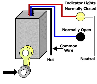
A limit switch has at least two sets of contacts: "normally closed" (NC) and "normally open" (NO) . When the switch is in the normal position (nothing touching the arm), the normally closed contacts pass electricity, so the diagram shows the normally closed indicator light as lit. When the switch is in the actuated position, the normally open (NO) contacts pass electricity, so the normally open indicator light is lit. The "common" wire carries electricity to both sets of contacts. The terminology of switches is the reverse of the terminology of gates: Switch contacts let electricity pass when they are closed. A gate lets grain pass when it is open.
Related topics
- Operation of an Export Elevator
- Operation of a Diverter Type sampler
- Operation of a Bulk Weighing Scale
- Testing a Bulk Weighing Scale
- Virtual Reality Models